| Home | Notes | Github |
|---|
Written: 29-May-2021
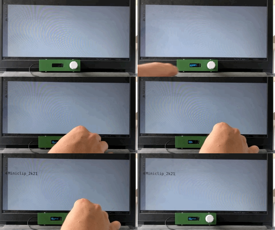
A USB Password Stick.
The idea for this project was to simulate a keyboard and type in a master password (for a password manager or something that is waaay to long to remember). So there needed to be a button. But to improve the functionality I decided to add a screen and use an encoder to navigate a basic menu.
Why? Because:
If you want to provide any feedback, in terms of digital security, or on anything for that matter please feel free to do so on the github page.
As an overview the hardware is:
The software was pretty simple, basically relying on pre-built libraries. After dealing with pure C and plain ol’ microcontrollers for the bigger project coming back to Arduino felt so easy, and I guess that’s the point.
I had a Sparkfun Pro Micro lying around, and with it’s native USB support this seemed like an ideal project for it.
Using the Pro Micro wasn’t without its flaws though. I’ve found (after research) that Pro Micros brick1 relatively easily. The cause is flashing the board 3V board with 5V firmware or vice versa2. What didn’t help is the knockoff I had3 didn’t have any markings, and so the first flash was a gamble4… which didn’t pay off5.
This is potentially fixed by using the 8 second long boot loader by shorting resent to GND in quick succession, however I’ve not found this any use as it’s never long enough to re-program the device. Alternatively the method that did work was re-flashing the Arduino firmware using the Arduino as a programmer method. The pin-out I used was as follows:
| Arduino Uno Pin | Pro Micro Pin | Note |
|---|---|---|
| 5V | VCC | ~ |
| GND | GND | ~ |
| 10 | RST | RST |
| 11 | 16 | MOSI |
| 12 | 14 | MISO |
| 13 | 15 | SCK |
The first code I wrote was to get the typing/keyboard functionality working. Initially I was going to work out how to Use the board as a HID but I found a simpler way. This involved (first testing with then) stripping out the useful parts of the KeyboardMessage example to give:
#include <Keyboard.h>

int buttonPin = 9;  // Set a button to any pin

void setup()
{
  pinMode(buttonPin, INPUT);  // Set the button as an input
  digitalWrite(buttonPin, HIGH);  // Pull the button high
}

void loop()
{
  if (digitalRead(buttonPin) == 0)  // if the button goes low
  {
    Keyboard.print("who-hoo");  // Send the String
    delay(1000);  // delay so there aren't a kajillion messages
  }
}Using the OLED was another joyously simple task. All I had to do was following a tutorial… this tutorial in fact. A couple of things to note: - Make sure you match the voltage of the OLED with the voltage of the Pro Micro Board you use (i.e. 5V OLED for 5V Pro Micro etc.). - Ensure you install Adafruit_SSD1306 library and all its dependencies. - Remember to add a display.display(); after each text change.
Pin-out on the pro micro is:
| OLED | Pro Micro |
|---|---|
| VCC | RAW |
| GND | GND6 |
| SCL | 2 |
| SDA | 3 |
Adding the encoder was a little harder, but only because I had to find the interrupt pins, and then start implementing some form of menu. Regarding reading the encoder, all the hard work has been done already. Thank you very much Matthias Hertel7. The pinout is as follows:
| Encoder | Pro Micro | #define |
Notes |
|---|---|---|---|
| GND | GND | ~ | ~ |
| + | RAW | ~ | 5V |
| SW | 7 | PIN_BUT |
Button |
| DT | TX0 | PIN_IN1 |
Interrupt 3 on proμ |
| CLK | RX1 | PIN_IN2 |
Interrupt 2 on proμ |
Copying out the backbone of the example sketches just leaves the program logic to contend with.
This included deciding on how the menu structure8 would work in the code etc. My flow is as such:
This appeared to work perfectly using the test code!
I wanted to open source this project, and thought it poor security to upload all my passwords to the internet. So I created a second file - holder-file.h - to house all the passwords.
This also included some variables for the “lost” screen which shows at boot up. I’d not recommend putting your whole name and your phone number, so I’ve just put “Dunc” and my flatmates phone number.
I created a dummy version for reference which is cloned with the repo9. Remember to update the list_max to the number of passwords you have.
All the files are on the github repo for this project, but it’s also below for reference:
The combined pinouts from above:
| Pro Micro | To: |
|---|---|
RAW |
Encoder + |
GND |
Encoder GND |
TX0 |
Encoder DT |
RX1 |
Encoder CLK |
7 |
Encoder SW |
RAW |
Screen VCC |
GND |
Screen GND |
2 |
Screen SCL |
3 |
Screen SDA |
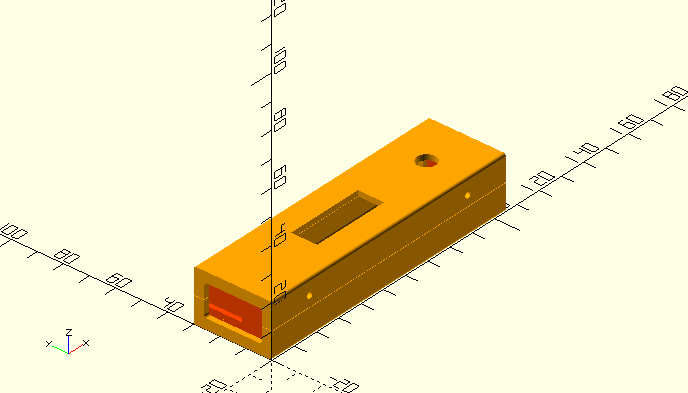
aka. the shell. For the case I used Heartman’s ultimate box maker10, with dimensions to allow the Pro Micro + Cable (which I was planning on gluing in place) rotary encoder and some wiggle room. There were several modifications made: - A hole was cut for the Encoder in the top shell - Another was cut for the screen - A cut was made in one of the end plates to allow a cable to be slid in. - Finally several dimensions were changed in the shell scripts so M2 bolts are reasonably self tapping.
For the self tapping holes an exterior hole of 2.4mm and an interior hole of 1.7mm seemed to work. The quality of your printer may help or hinder. For me a rough print seemed to result oblong hole allowing the screw to smoosh the plastic around without splitting the print.

Files can be downloaded here or from the github repo.
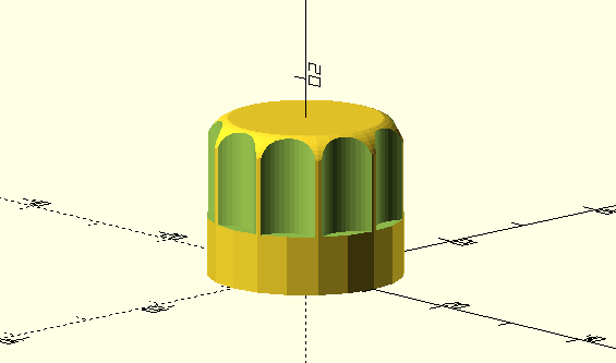
My encoder didn’t come with a knob, this meant I could create my own. Luckily Steve Cooley had already created a parametric knob using OpenSCAD so I toyed with the parameters to create this:

Only one modification was required, which was adding more cutout for the shaft without flat spot on it. This meant adding the following line within a difference bracket in the make_the_knob module: openscad translate([0,0,-0.1])cylinder(shaft_height-7,shaft_radius+0.1,shaft_radius+0.1); Where the 7 is the length of the flat spot along the shaft.

Due to the way Arduino works it’s bloody hard to properly brick ’em.↩︎
I don’t know why.↩︎
Naughty me 😬↩︎
It doesn’t have to be a gamble (I think). Check the crystal frequency, 16MHz is 5V and 8MHz is 3V.↩︎
A swift helping of karma if I’ve ever seen it.↩︎
Pretty Self Explanatory.↩︎
And Arduino obvs.↩︎
A fancy phrase for two lists who happen to line up. Praise goes here to the Arduino String() datatype.↩︎
The passwords and phone number in the public repo may or may not be fake?↩︎
Chunks of the code appear to be in french, including “Coque()” which is fun! 🥖️🇫🇷️🥐️.↩︎