| Home | Notes | Github |
|---|
Written: 21-Aug-2021
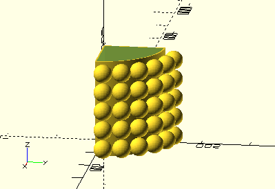
The design is inspired by bitulni’s lights however what I’m wanting is a quarter cylinder to sit in the corner of a room so the concept was adjusted accordingly. My original idea for the light is something like this:

The sizing of the lamp depended on several things, but was worked out mathematically.
Plan is to use 1m of LED strip - conveniently measured at 30 LED/m - giving me 30 LEDs to play with. This means we can go for a 5 Rows of 6 LEDS1. Calculating the arc of the quater circle - \(c_q\) - is:
This means the radius of the cylinder - \(r_c\) - is:
The ping-pong ball radius, \(r_p\), is approx 40mm, to check they fit in a straight line the following must be met: Where \(\) comes from the image below, and the angle is the angular space occcupied by each ball.
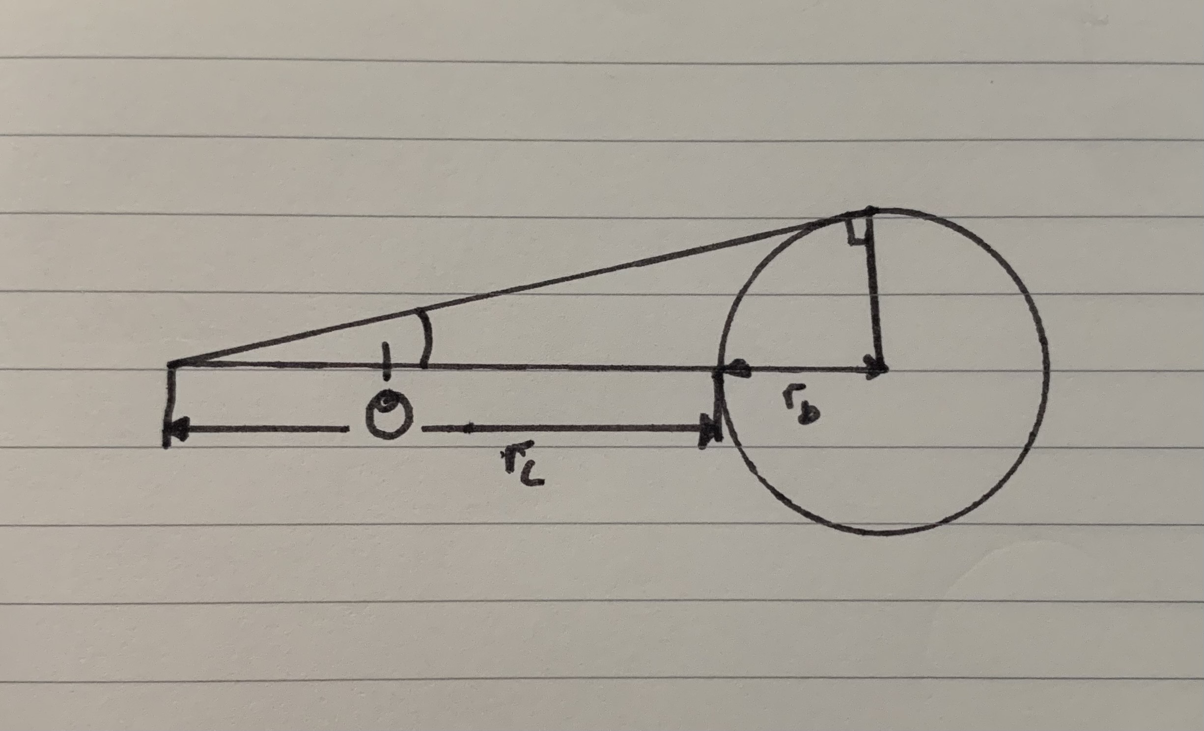
To find theta:
Which is greater than zero2, so it should fit… just3.
The height of the lamp is pretty simple to calculate:
Now with the sizing done the actual design can be worked out.
I fancied to use OpenSCAD, because:
Open scad is a bit primitive, but its an interesting concept for anyone who fancies giving it a bash. I think the thing I enjoyed the most about it is how everything is parametric (basically) by default. The worst bit is either having to work out the math so things like hole spacing work out nicely, or the pain in the ass that shelling is.
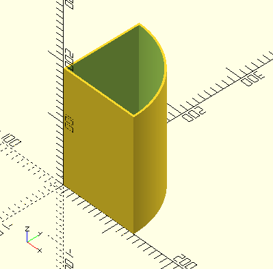
The structure is simply a hollowed quarter cylinder I was planning on 3D printing and then drilling holes as required4.
$fa = 1; //Adjust for Render Quality.
$fs = 0.1;

cheigh = 100; // Total Height
crad = 127; // Exterior Radius
tn = 3; // Wall Thickness

module q_tube(height,rad){ // Quater Cylender Function
intersection() {
cylinder(height,rad,rad);
cube ([rad,rad,height]);
}}

module m3_bsupp(thick){ // Support point for M3 Bolt
    difference(){
        cube([6,6,thick]);
        translate([3, 3, -1])
        cylinder(thick+2,3.2/2,3.2/2);
    }
}

// Shelling the part
difference(){
    q_tube(height=cheigh,rad=crad); // Exterior
    intersection(){
        translate([0,0,-1])
        q_tube(cheigh + 2, crad-tn);
        translate([tn,tn,-1])
        cube ([crad,crad,cheigh+2]);
    }
}

// Adding Tabs for screwing parts together
tn = 2.9; // Adjusting tn to ensure overlap of parts
translate([tn,crad-tn-6,0])
m3_bsupp(tn);
translate([crad-tn-6,tn,0])
m3_bsupp(tn);
translate([tn,tn,0])
m3_bsupp(tn);
However, this would’ve taken too much time and filament for it to be acceptable to sneak on the 3D printers at work. As such I modified the structure to contain only the essential surfaces as needed. This involved a set of quarter circle frames, held with central column (made from recycled carbon fibre tubing) with supporitng spars for stifness / robustness all connected with M3 nuts+bolts5.
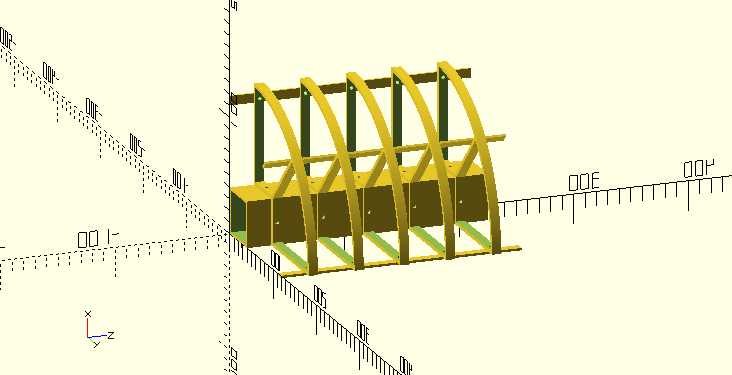
What I found is that messing round with carbon fiber is a pain, and the same the spars were strong enough on their own, resulting in an even more skeleton structure:
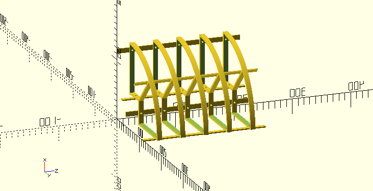
Original OpenSCAD code for these can be found below. All code (SCAD or otherwise) can be found on the github repo (including any revisions).
$fa = 1; //Adjust for Render /uality.
$fs = 0.1;

cheigh = 8; // Total Height
crad = 127; // Exterior Radius
tn = 3; // Wall Thickness
centre_width=40; // Thickness of Central Pillar
sd = 0.1; // Small difference
riv_r = 3.2/2; // rivet radius

module q_tube(height,rad){ // Quater Cylender Function
    intersection() {cylinder(height,rad,rad); cube ([rad,rad,height]);
}}

module m3_bsupp(thick){ // Support point for M3 Bolt
    difference(){
        cube([6,6,thick]);
        translate([3, 3, -1]) cylinder(thick+2,3.2/2,3.2/2);
    }
}


difference(){
    // Union to keep it as one child.
    union(){
        // Creating Shelled Q Tube
        difference(){
            // Creating Shelled Q Tube
            difference(){
                q_tube(height=cheigh,rad=crad); // Exterior
                intersection(){
                    translate([0,0,-1]) q_tube(cheigh + 2, crad-tn);
                    translate([tn,tn,-1]) cube ([crad,crad,cheigh+2]);
                }
            }

        // Subtracting the inner cube
        translate([-sd,-sd,-sd]) cube([centre_width+sd,centre_width+sd,cheigh+2*sd]);
        }

        // Creating the Wall to mate with the Center pole
        difference(){
            cube([centre_width+tn,centre_width+tn,cheigh]);
            translate([-sd,-sd,-sd])
            cube([centre_width+sd,centre_width+sd,cheigh+2*sd]);
        }
    }
    // Cutting Holes for Rivets
    //    Around the Central Column
    translate([centre_width-sd,centre_width/2,cheigh/2]) rotate([0,90,0]) cylinder(tn+2*sd,riv_r,riv_r);
    translate([centre_width/2,centre_width-sd,cheigh/2]) rotate([-90,0,0]) cylinder(tn+2*sd,riv_r,riv_r);
    //    Around the Edge for Stability
    translate([(crad-3*2*riv_r-tn),-sd,cheigh/2]) rotate([-90,0,0]) cylinder(tn+2*sd,riv_r,riv_r);
    translate([-sd,(crad-3*2*riv_r-tn),cheigh/2]) rotate([0,90,0]) cylinder(tn+2*sd,riv_r,riv_r);

}
// Adding Middle Spar with Holes
difference(){
    // Spar
    rotate([0,0,45]) translate([-tn/2,-tn/2,0]) cube([crad,tn,cheigh]);
    // Minus Middle Box
    translate([-tn,-tn,-sd]) cube([centre_width+tn, centre_width+tn,cheigh+2*sd]);
    // Munus Hole
    rotate([0,0,-45]) translate([-tn/2-sd,crad-3*2*riv_r-tn,cheigh/2]) rotate([0,90,0]) cylinder(tn + 2*sd,riv_r,riv_r);

}// Support Spar
$fa = 1; //Adjust for Render quality.
$fs = 0.1;
bh = 210; // Length of spar (heigh of lamp)
bth = 2; // Wall thickness
bw = 40; // Size of Central Suppourt
chei = 8; // Height of each Strip
riv_r = 3.2/2; // Rivet Radius
sd = 0.1; // Small Difference
no_holes=5; // Number of holes on a stick
// For with Central Colomn:
//step = (bh - chei)/(no_holes-1); // Step value between Holes
// For No Central Colomn, Just these sticks:
pp = 40; foot = 5; step = (bh-2*foot-pp)/(no_holes-1); // Step value between Holes
echo(step=step);
translate([0,0,sd])
difference(){
cube([bh,chei,bth]);
// Cutting Holes
for (i = [0:no_holes-1]){
// With Column
//translate([chei/2 + i*step,chei/2,-sd])
// Without Column
translate([foot +pp/2 + i*step,chei/2,-sd])
cylinder(bth+2*sd,riv_r,riv_r);
}
}A test piece was first riveted6 together to check how the rivets fitted. It helped to run a 3mm drill bit to clean most of the junk out of the holes.
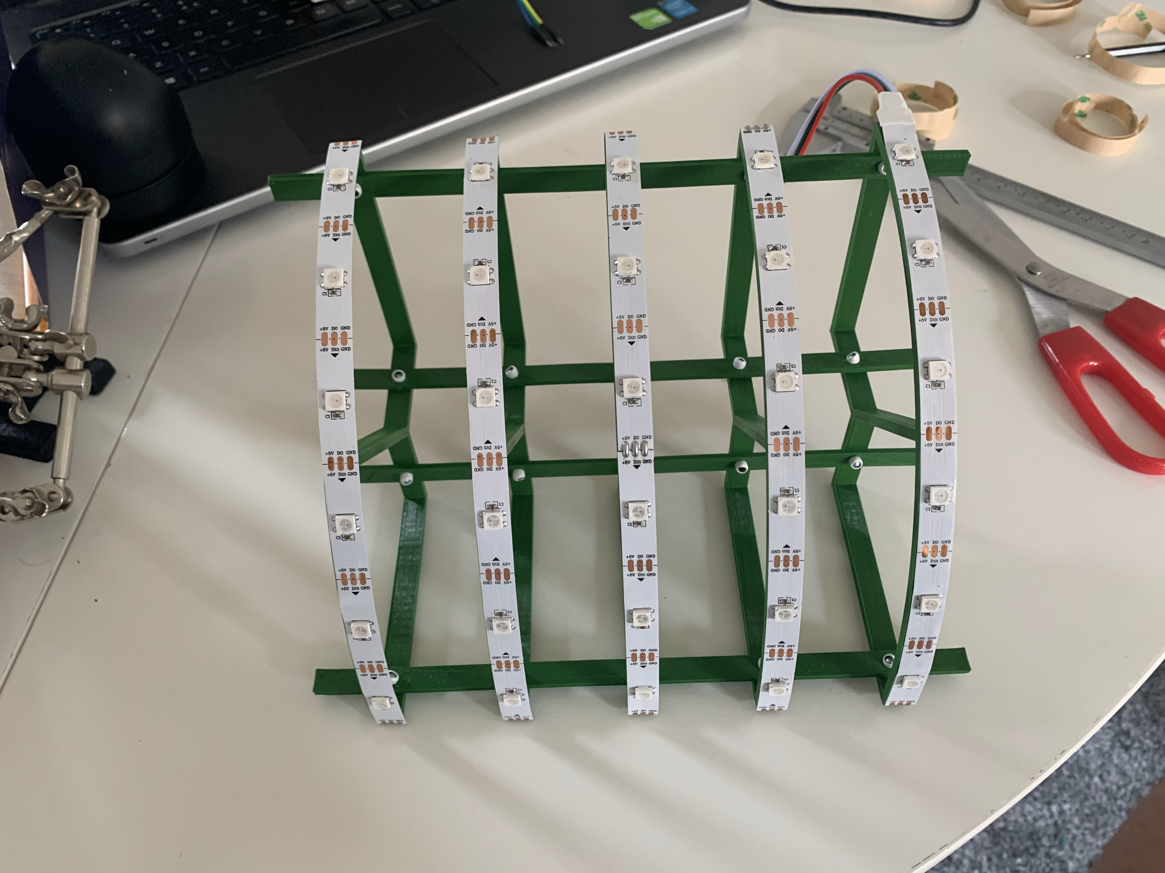
I found the holes on the 3D print had gotten a bit oblong - from the orientation of the hole when printing - but this seemed to help. After a successful test a frame was riveted together, marking the end of the mechanical build:
We (or you) could go for other configs, but this was a nice initial guess at something remotely square.↩︎
After doing the math, any cylinder radius \(\) should work↩︎
Drilling holes isn’t exactly in the 3D printing spirit, but it’s the most flexible option.↩︎
This eclectic mix of things are what ended up in the scrap pile at work.↩︎
The plan changed because of the tides of what was scavengable at work, and I riveted the parts. This worked very well (using very soft rivets) however care had to be taken not to split parts.↩︎