
| Home | Notes | Github |
|---|
Written: 24-Aug-2021
The LED strips were cut to length, and the backing peeled off. This was stuck to the frame pieces using the marks from the 3D print1 to align the middle LED to keep them consistent.
These were then soldered together, first by doing power pins with some solid core wire that was to hand:

Important to note was the fact the LED strip alternated direction (note the small arrows on the data pins) on each neighboring part. This is vital to allow the data lines to be daisy chained2 together.
The ends were then reinforced with hot glue to prevent them peeling up3 with extra going on the pre-soldered end.
The PCB position was defendant on the length of the LED wires. The original intention was to re-solder them to a nice connector, but at this point I was a bit over getting this project polished up4
This got attached to one of the spars using liberal amounts of hot glue, which worked a treat.
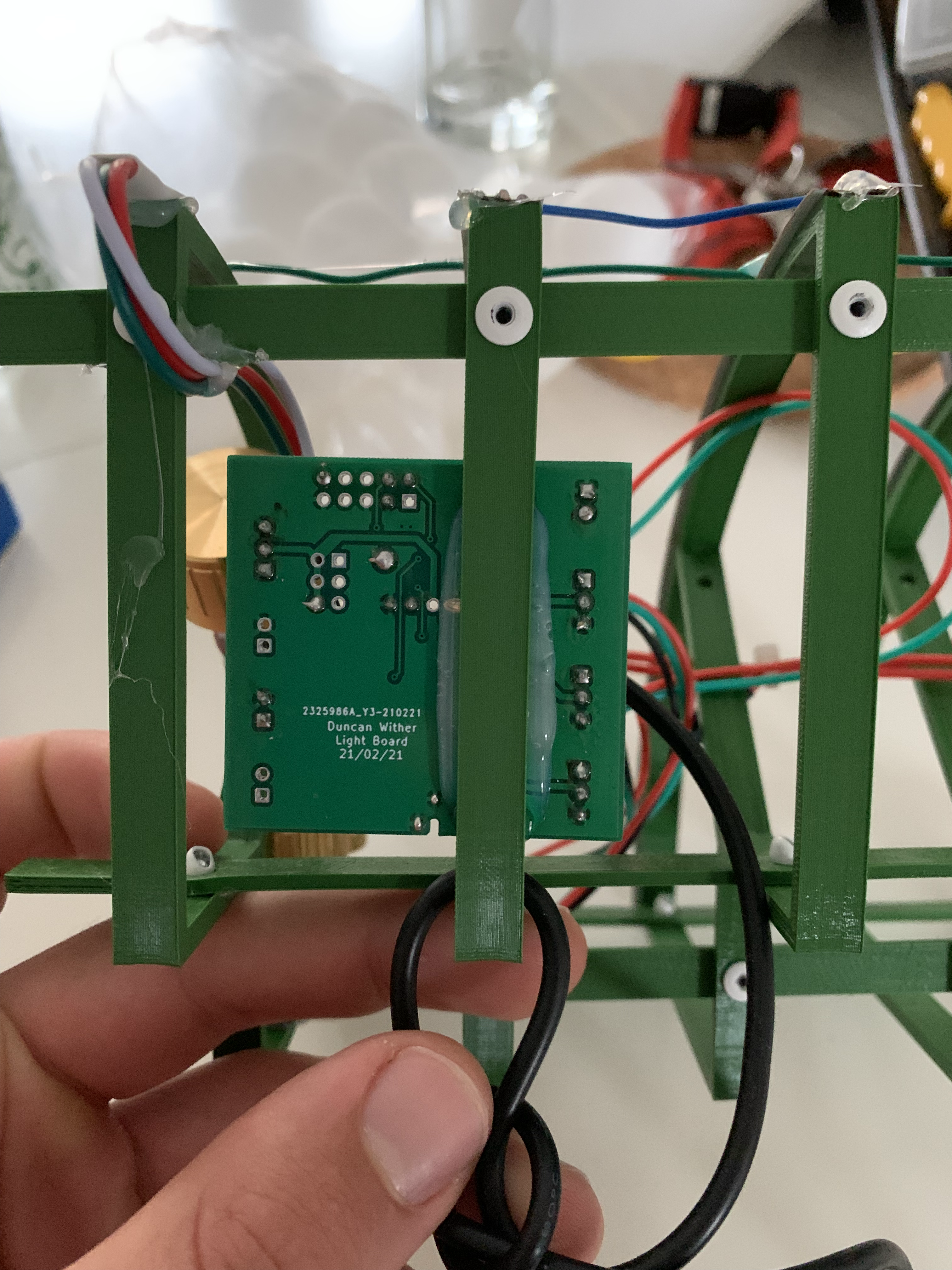
Originally I was going to put the potentiometers with the axis of the dial parallel to the axis of the cylinder - or with the knobs sticking out the end in simpler language - but this required another 3D print which I hadn’t designed, let alone printed. As such they got the hot glue treatment too:
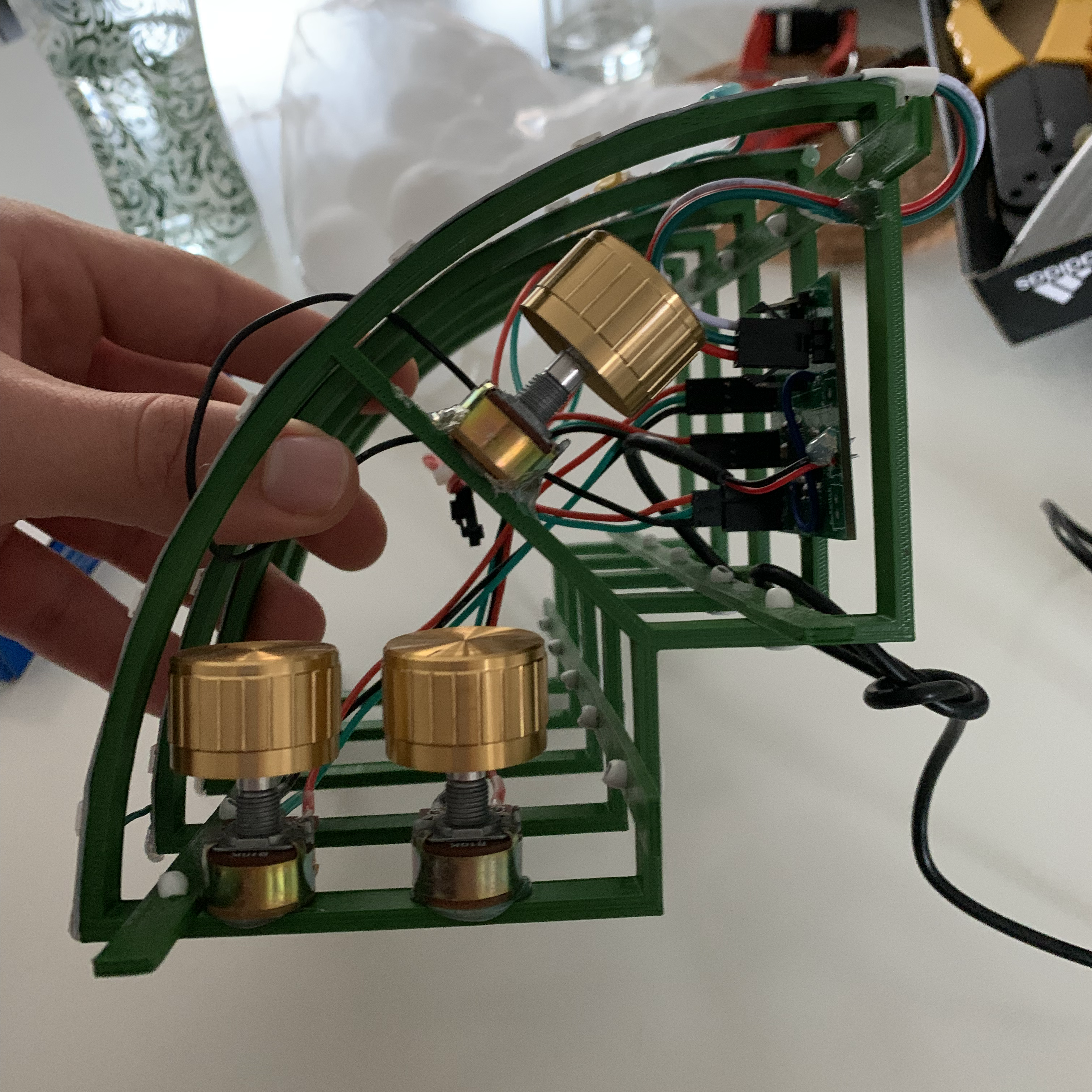
The wires for these were cut to a random length with the plan of shortening in place. Shockingly I didn’t do this, and instead wrapped it round a couple bits of the skeleton to keep them out of the way-ish. Also the pots I used had an optional switching action, which I was considering for the master on/off switch, hence the extra cabling, but it wasn’t used.
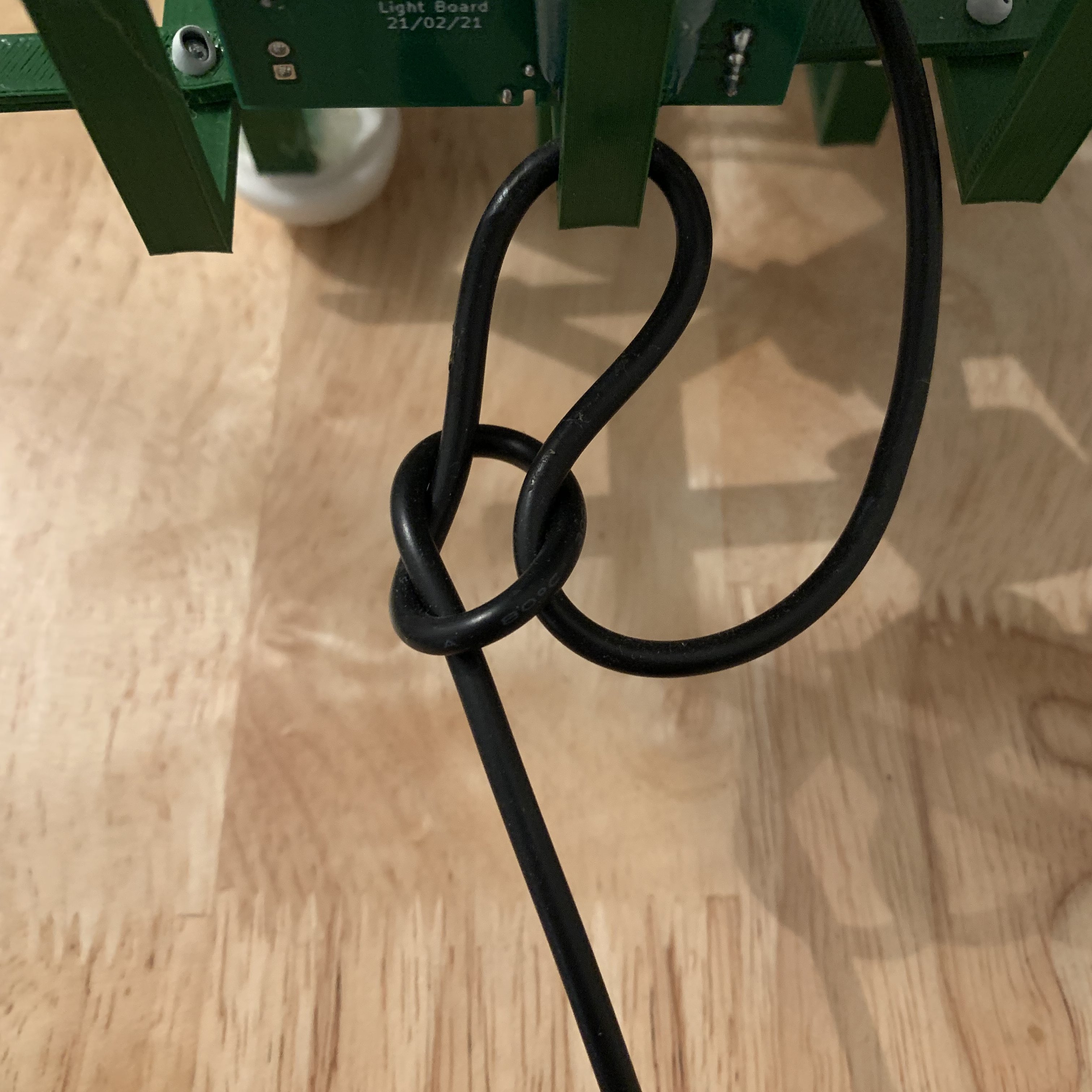
The only other thing was to tie a knot in the power cable for strain relief. This is tied the wrong way round - and is a bit overkill - but you get the gist:
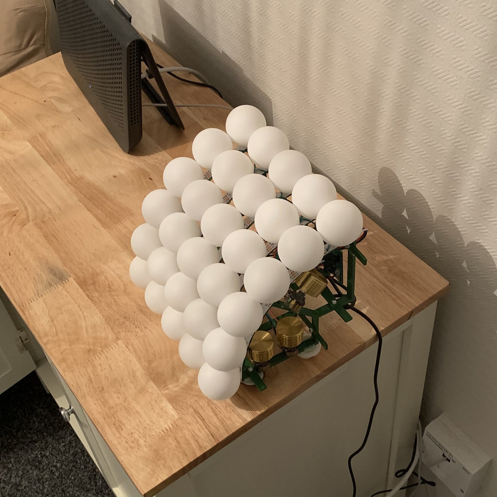
Despite overestimating the size of the balls5 and underestimating the cylinder radius - by omitting the 2mm of the LED thickness - the ping pong balls didn’t fit.
This is one of the biggest flaws of the design6, however it didn’t hold me back7 and the placement was fudged. With the addition of a small dab of hot glue to secure the balls we’ve got ourselves a complete project 🍾
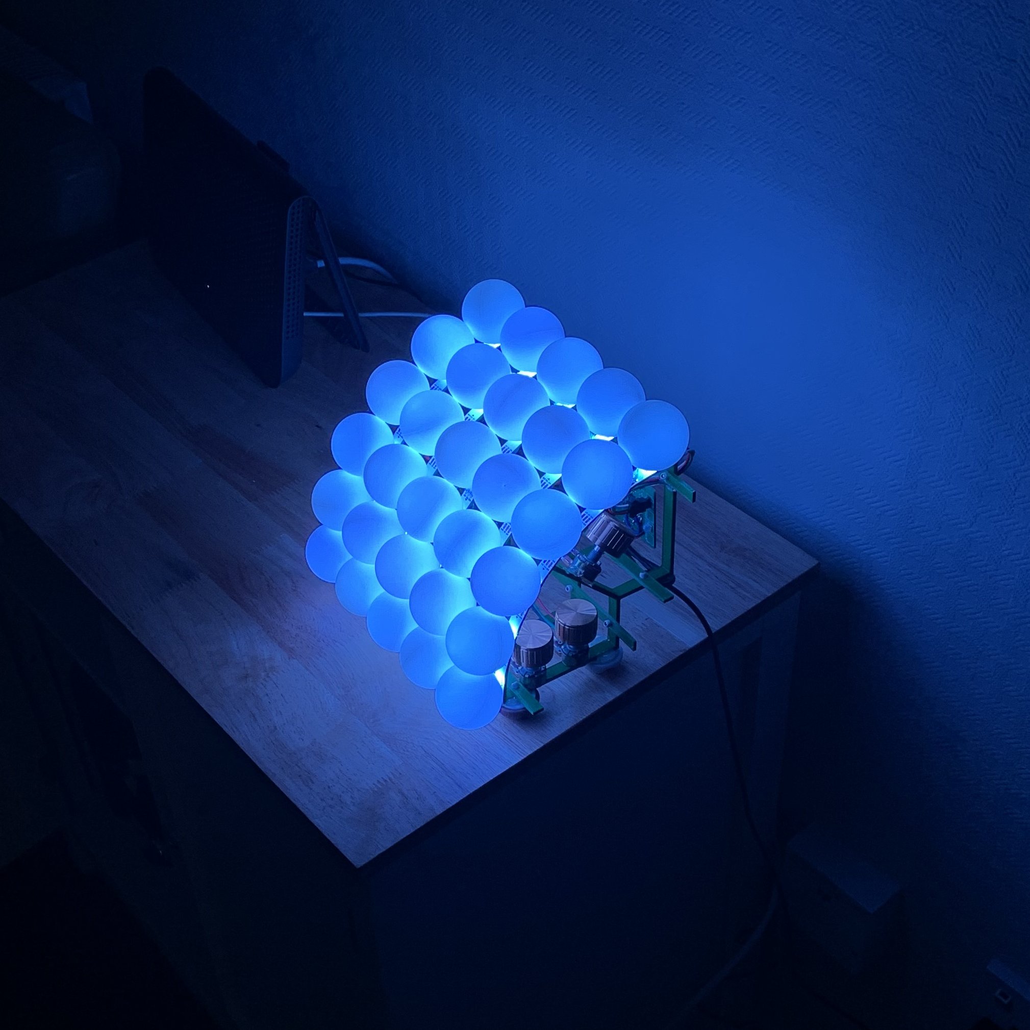
Its always good to re-visit the initial goals at the end of a project, to see how you’ve done and how things have changed from you’re initial expectations. To reiterate them:
I built this lamp for a number of reasons:
- I needed a lamp.
- Or at least I did when I started this project.
- Education
- Primarily in integration and the actuality of building a prototype
- Something nice for interviews
- Again primarily as something to talk about when looking at completing projects / the last hurdle for electronics development.
- Also to give me confidence when talking about developing code on microcontroller
It was an education and was good for helping me learn more about hands on problem solving and integration issues.
Confidence was the big boost. Previous to this all I’d done is futz around on Arduinos and other dev boards, but now having now put my own code on a microcontroller on my own board is really cool. This project - in all its difficulty - is worth is just for that bridge between my practical knowledge.
Saying that, programming the board was surprisingly easy. After connecting the programmer to the board it read the chip and just worked™️. There was an issue with the second board, but that was an easily found solder-less pin on the microcontroller, and after fixing that it worked no problemo. I don’t know if that’s just ST’s secret sauce or something, but I was surprised how simple it was.
That’s it. Its far from perfect: there’re a couple mistakes to fix for a mk1.1 (as and when I can muster the time/effort to do so) and some needed improvements to make (like adding the pots to the PCB) which’ll form the mk2 but overall I’m pretty happy.
If you think of any glaring mistakes please make an issue on the github: I love learning from my mistakes, so don’t hold back!
I’m aware this has the potential to not be super consistent, but I used the same code each time for the print and it seems to be alright.↩︎
This was a late change - because by this point I’d completed the software - from just doing six parallel rows, but I thought this’d give more opportunity to do something funky 🥳 with colours 🌈 in the future.↩︎
There was a high peel risk since I had forgotten to (or just did it very badly) measure the width of the LED strip for the frame parts.↩︎
Is it obvious I’m just racing to the finish line now? 🏎️↩︎
Sampling 3 gave me 39.6±0.1mm in diameter.↩︎
Certainly a failing of the primary design. Something will have to change for the mk2, but for now fudging it is good enough.↩︎
The balls not fitting didn’t hold me back… for too long.↩︎