| Home | Notes | Github |
|---|
Written: 23-Aug-2021
The software side was meant to be pretty simple. This was the design:
And maybe include some buffers and filtering for bonus points.
Safe to say it wasn’t as easy as I imagined.
The first step was to prototype the code on the DISCO board.
To read the more than one channel on the ADC you need to enable direct memory access (DMA). The setup was as follows:
In the CUBE IDE Pin-out section: Select the ADC channels you want to use (i.e. ADC IN1, ADC IN2 and ADC IN3):
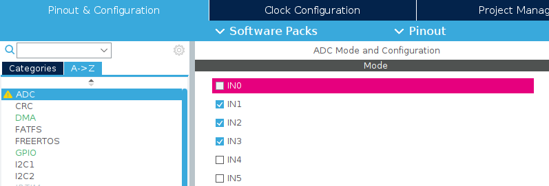
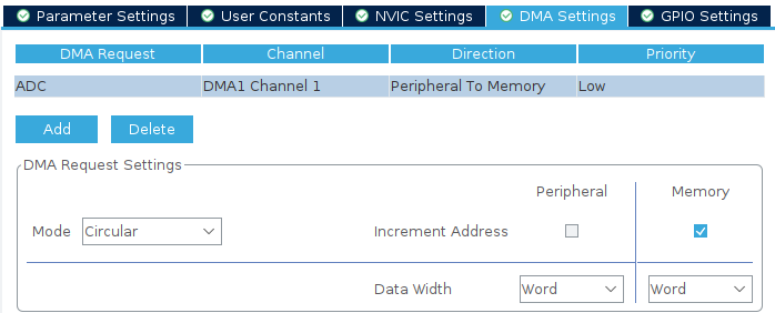
Then on the DMA tab add a new DMA Request for the ADC. The circular mode means it’ll keep updating as your code runs.
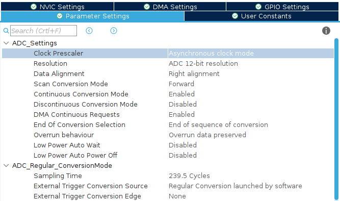
Then use the following parameters. Adjust the resolution etc. as necessary:
The code required is pretty simple. It is a variable to store the ADC values, and a line to start the ADC DMA:
uint32_t adc_values[3];
HAL_ADC_Start_DMA(&hadc,adc_values, 3);
The adc_values array will then keep being updated with the values thanks to the DMA interrupt system1.
Many thanks to this video for finally helping me to solve the multichannel ADC read.
Converting the values from the potentiometers - which are meant to represent the HSV values - to the LED values - RGB of course - was somewhat trivial, but a fun little bit of mathematics based on the HSV Wikipedia page:
uint8_t * conv_hsl_2_rgb(uint16_t hue, uint16_t saturation, uint16_t light) {

    static uint8_t rgb[3];
    float f_red;
    float f_grn;
    float f_blu;

    float ADC_max = 4096; //2^12

    float f_hue = (float) hue;
    float f_lig = (float) light;
    float f_sat = (float) saturation;

    // Converting to degrees or [0,1]
    f_hue = f_hue * 360 / ADC_max;
    f_lig = f_lig / ADC_max;
    f_sat = f_sat / ADC_max;

    // Using the geometric method:
    float chroma = (1 - fabs(2 * f_lig - 1)) * f_sat;
    float h_dash = f_hue / 60;
    float xval = chroma * (1 - fabs(fmod(h_dash, 2.0) - 1));

    if (h_dash < 1) {
        f_red = chroma;
        f_grn = xval;
        f_blu = 0;
    } else if (h_dash < 2) {
        f_red = xval;
        f_grn = chroma;
        f_blu = 0;
    } else if (h_dash < 3) {
        f_red = 0;
        f_grn = chroma;
        f_blu = xval;
    } else if (h_dash < 4) {
        f_red = 0;
        f_grn = xval;
        f_blu = chroma;
    } else if (h_dash < 5) {
        f_red = xval;
        f_grn = 0;
        f_blu = chroma;
    } else{// if (h_dash < 6) {
        f_red = chroma;
        f_grn = 0;
        f_blu = xval;
    }

    float bias = f_lig - chroma / 2.0;

    f_red += bias;
    f_grn += bias;
    f_blu += bias;

    // Converting Back to [0,256]:
    f_red = f_red * 256;
    f_blu = f_blu * 256;
    f_grn = f_grn * 256;

    // Converting to int and adding to array.
    rgb[0] = (uint8_t) f_red;
    rgb[1] = (uint8_t) f_grn;
    rgb[2] = (uint8_t) f_blu;

    return rgb;
}The LED take a specific PWM signal as specified in the WS2812B Datasheet. Initially I thought it best to run a 3 bit signal (with the middle bit being the data bit per say), however after several attempts I found another tutorial which suggested otherwise. It used an array with all possible 256 bit values and then just selected the correct bits to send over SPI.
This requires the chip to be running at maximum clock speed, and to do that go to the Clock Configuration tab in the CubeIDE and set it as is shown:

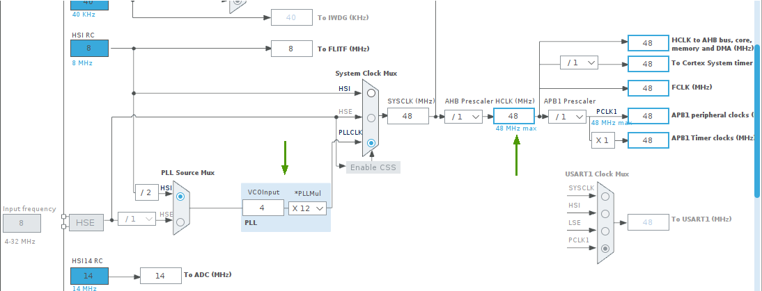
HCLK is 48MHz. I think this required adjusting the PLLMul variable."Once you’ve sorted the clock the setup for the SPI stuff is pretty simple. First, go back to the Pinout view and go to Connectivity-> SPI1 and set the parameters as follows:
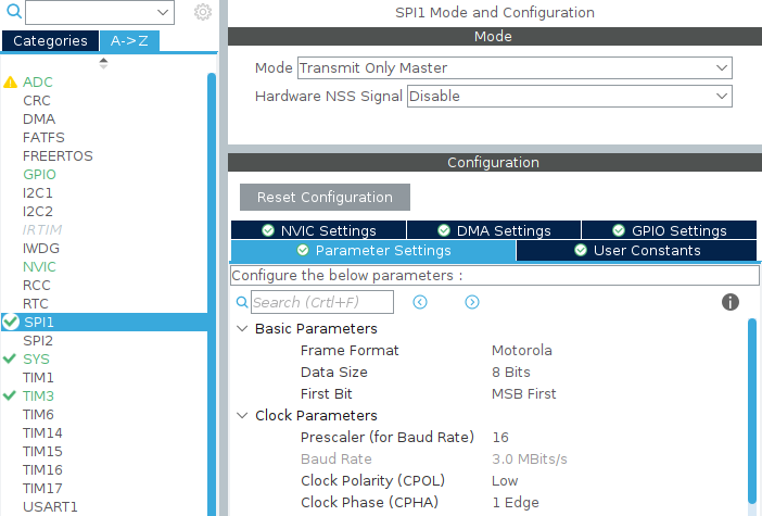
The Code is much larger, but mainly because the array is spelled out in full. The array is on the tutorial. Without the array the code looks like this:
uint8_t * uint8t_to_spi (uint8_t value)
{
  // Array Here:
  const uint8_t leddata[256*4] = {};

  int i;
  static uint8_t spi[4] = { 0, 0, 0 ,0};
  for (i=0;i<4;i++){
      spi[i]=leddata[4*value+i];
  }

  return spi;
}
I also created a little helper function to create the array of data to send:
uint8_t * color_to_spi (uint8_t r, uint8_t g, uint8_t b){
    static uint8_t c_arr [4*3]; // Because 4 bytes of spi for every byte of colour, and 3 colours.
    uint8_t colours[] = {g,r,b}; // order for the spi leds
    int c,i; //iterators
    uint8_t *spi_val; // holder for the spi values array
    for (c=0;c<3;c++){
        // iterating over the colors.
        spi_val = uint8t_to_spi(colours[c]);
        for (i=0;i<4;i++){
        // sending the values to the array
            c_arr[i+4*c]=*(spi_val+i);
        }
    }
    return c_arr;
}
And finally a little function for sending the data:
void spi_send (uint8_t r, uint8_t g, uint8_t b, int no_of_leds){
    // Step 1: convert color to spi bits for one LED
    uint8_t *pSPIvals = color_to_spi(r,g,b);

    // Step 2: create array for multiple leds
    uint8_t spi_data[3*4*no_of_leds];
    int led,i;//iterators
    for (led=0;led<no_of_leds;led++){
        for (i=0;i<12;i++){
            spi_data[i+12*led]=*(pSPIvals + i);
        }
    }
    // Step 3: send spi signal
    HAL_SPI_Transmit(&hspi1, (uint8_t*) &spi_data, 12*no_of_leds, 10);
}This is all tied together in the main function, shown below without the CUBE generated code.
One thing of note was some averaging performed. This was to smooth any transitions, and to sneak in a little circular buffer for a bit of technical fun.
int main(void)
{
    /* USER CODE BEGIN 2 */
    // Showing initialisation has begun
    HAL_GPIO_WritePin(GPIOC, LD4_Pin, GPIO_PIN_SET);

    HAL_TIM_PWM_Start(&htim3, TIM_CHANNEL_4);

    uint32_t adc_vals[3];
    HAL_ADC_Start_DMA(&hadc,adc_vals, 3);

    //Showing initialisation has ended.
    HAL_GPIO_WritePin(GPIOC, LD4_Pin, GPIO_PIN_RESET);

    int array_len=100;
    int array_pos=0;

    int j;

    // ADC Arrays
    uint16_t adc1_array[array_len];
    uint16_t adc1_ave = 0;

    uint16_t adc2_array[array_len];
    uint16_t adc2_ave = 0;

    uint16_t adc3_array[array_len];
    uint16_t adc3_ave = 0;

    uint8_t *phsl_val;


    for (j=0;j<array_len;j++){
        adc1_array[j]=0;
        adc2_array[j]=0;
        adc3_array[j]=0;
    }

    /* USER CODE END 2 */

    /* Infinite loop */
    /* USER CODE BEGIN WHILE */
    while (1)
    {

        adc1_array[array_pos]=adc_vals[0];
        adc2_array[array_pos]=adc_vals[1];
        adc3_array[array_pos]=adc_vals[2];
        if (array_pos < array_len){
            array_pos ++;
        } else {
            array_pos = 0 ;
        }


        //taking circular buffer ave
        adc1_ave=0;
        adc2_ave=0;
        adc3_ave=0;
        for (j=0;j<array_len;j++){
            //adc_ave += (adc_array[j]/(16*array_len)); // for adc_ave is uint8_t
            //adc_ave += (adc_array[j]/(array_len)); // for adc_ave is uint16_t

            adc1_ave += (adc1_array[j]/(array_len));
            adc2_ave += (adc2_array[j]/(array_len));
            adc3_ave += (adc3_array[j]/(array_len));
        }

        // Converting RGB to Colors
        // The hsl->rgb takes raw values from ADC (Max 4095)
        //phsl_val=conv_hsl_2_rgb(adc_vals[0],adc_vals[1],adc_vals[2]);
        phsl_val=conv_hsl_2_rgb(adc1_ave ,adc2_ave ,adc3_ave );


        // Sending Data
        spi_send(*(phsl_val),*(phsl_val+1),*(phsl_val+2),10);

        // Delay Code
        HAL_Delay(1);
        /* USER CODE END WHILE */

        /* USER CODE BEGIN 3 */
    }
    /* USER CODE END 3 */
}
All the code + full project files2 can be found on the github repo.
Up to this point I’ve been doing all the development work using the DISCO board, and code needed to be transferred over to work on the chip I’d used. Luckily all this required was to make a new project using the STM32F030C6T6 chip. The same setup steps were then repeated in the IDE for generating the backbone of the main.c file and all of the HAL functions. The chunks of code (helper functions and the main loop) were then just copied and pasted and hey-presto! it worked. I have to say the ecosystem/HAL stuff was great for that and I was very impressed how easy this step was.
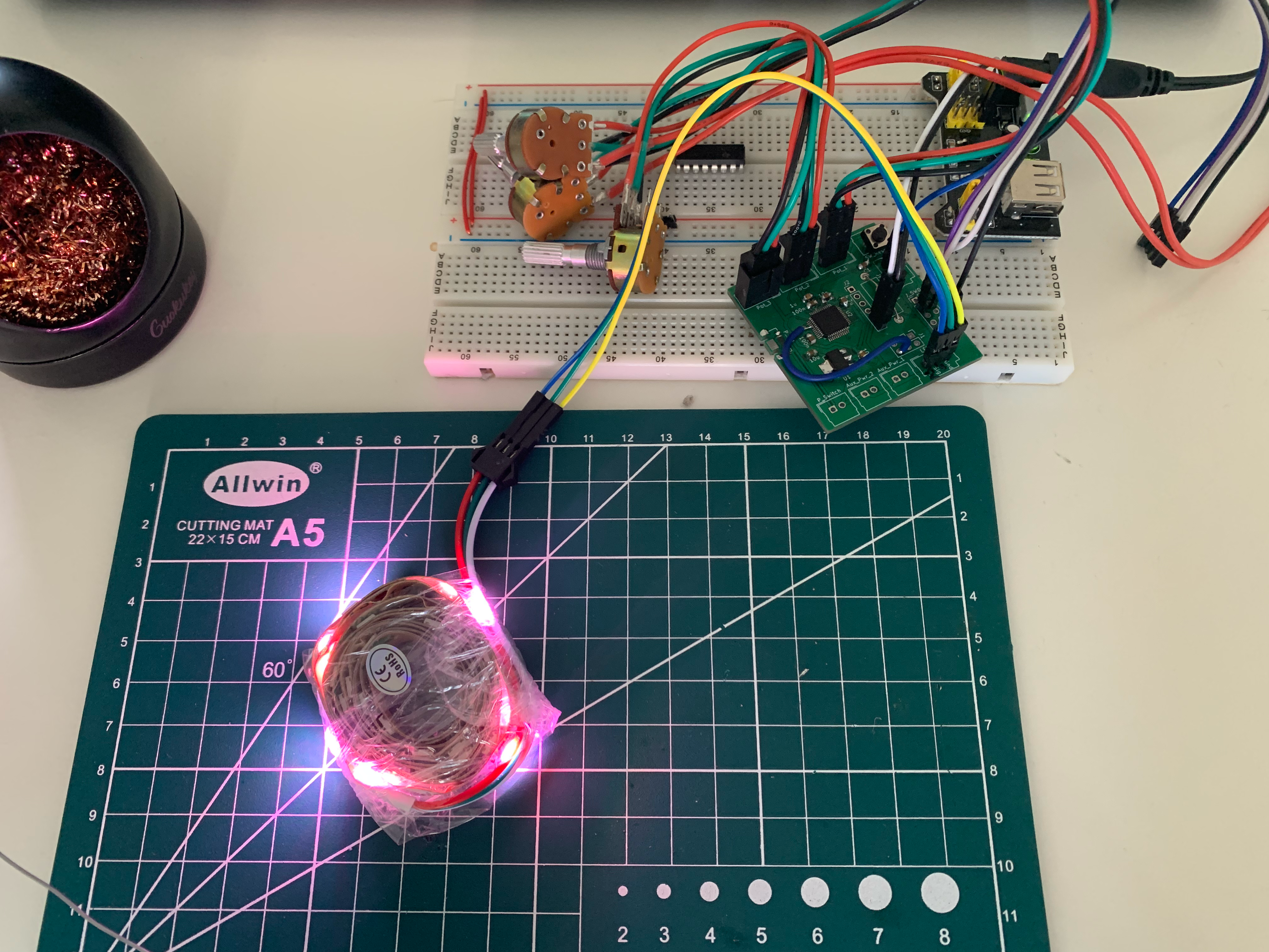
The two big challenges faced through this process were:
Reading multiple channels on the ADC was difficult mainly because I wanted to avoid learning anything to do with DMA to try and simplify the task. This was the wrong moment to try and simplify. The DMA was pretty simple to implement3 (even if I don’t fully comprehend it) and only required minimal finagling.
The method of sending pulses was planned initially to be a PWM wave with changing pulse widths, although I couldn’t get it to work4.
The second thing I was thinking of trying was to manually do it with pin high and low style commands, esp. given how much computational headroom I think I had on the chip, however I wasn’t sure of the timings that would produce coming out of the chip.
This is the third of the two issues. As is slightly more low key, but rather more pervasive than the others. A general stiffness in the backbone of this project if you will.
Linux is great imo and it’s what I use. For this project, however, it was a pain. I’ve found for some embedded stuff the resources aren’t there. Luckily the STM32Cube IDE is available, and the open source stlink software is available for programming, but more powerful tools like live debugging wasn’t an option. It made programming a bit more of a pain, but luckily I had the DISCO board for testing, and I got there in the end. It’s perfectly possible to do, but just a heads up for someone following in my footsteps.
Full disclosure: I don’t fully understand what’s going on with the DMA, however it works enough for me to be able to move on to the next stages of the project.↩︎
including the detritus from saved code / library attempts etc.↩︎
Even if there were no recent tutorials. Perks of using discontinued parts I guess.↩︎
Not to say someone else couldn’t↩︎